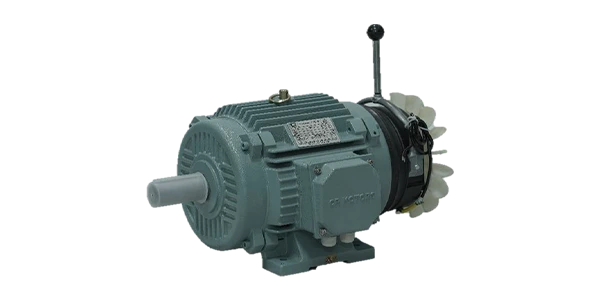
Single Phase Brake Motor
1Ph - Aluminium / Cast Iron Series
( 80 - 112 Frame - 2880 RPM / 1440 RPM / 960 RPM )
Not every site has access to a three-phase supply, and for those situations CR Motors produces single phase motors that perform reliably in single-phase power conditions. As experienced single phase motor manufacturers, we supply motors suited to a broad range of small to medium-scale industrial and commercial applications.
Our single phase industrial motors are used in pumps, fans, small compressors, light conveyors, and general machinery where three-phase infrastructure is unavailable or not practical. They are built with quality copper windings and precision-balanced rotors, and they deliver smooth operation, consistent starting torque, and low noise levels in service.
We also manufacture single phase brake motors for situations that require controlled stopping in single-phase power environments. The integrated electromagnetic brake engages on power cut-off, giving precise stopping for small hoists, conveyors, and packaging equipment.
As single phase brake motor manufacturers, we have put specific engineering attention into achieving reliable brake torque within a single-phase design. The brake mechanism is optimised for quick response and consistent performance across extended operating cycles.
Our single phase motors are available in capacitor-start, capacitor-run, and capacitor-start capacitor-run configurations, depending on what the starting torque and running performance requirements demand.
Talk to CR Motors about the right single phase motor for your application.
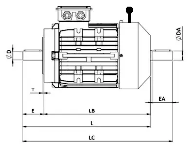
Dimensions & Electric Specifications
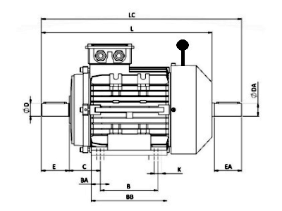
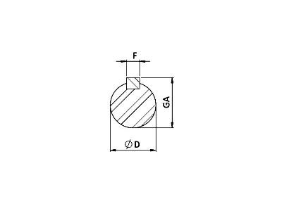
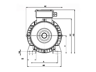
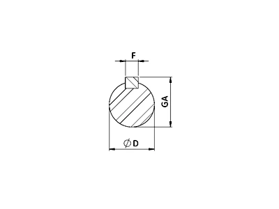
| Frame | A | AA | AB | AC | B | BA | BB | C | D | DA | E | EA | F | FA | GA | H | HA | HC | HD | K | L | LC |
|---|---|---|---|---|---|---|---|---|---|---|---|---|---|---|---|---|---|---|---|---|---|---|
| 80 | 125 | 38 | 154 | 157 | 100 | 30 | 125 | 50 | 19 | 19 | 40 | 40 | 8 | 8 | 21.5 | 80 | 15 | 154 | 220 | 10 | 340 | 385 |
| 90 S | 140 | 41 | 174 | 175 | 100 | 30 | 130 | 56 | 24 | 24 | 50 | 50 | 8 | 8 | 27 | 90 | 13 | 160 | 230 | 10 | 390 | 115 |
| 90 L | 140 | 41 | 174 | 175 | 125 | 30 | 155 | 56 | 24 | 24 | 50 | 50 | 8 | 8 | 27 | 90 | 14 | 160 | 230 | 10 | 410 | 465 |
| 100 L | 160 | 48 | 192 | 195 | 140 | 31.5 | 175 | 63 | 28 | 28 | 60 | 60 | 8 | 8 | 31 | 100 | 15 | 175 | 240 | 10 | 450 | 515 |
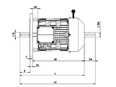
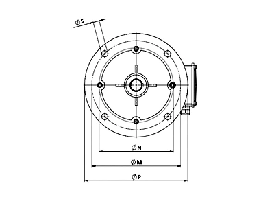
| Frame | FLANGE NUMBER |
P | M | N | S | L | LA | LB | LC | LD | T | D | DA | E | EA | F | FA | GC | GA |
|---|---|---|---|---|---|---|---|---|---|---|---|---|---|---|---|---|---|---|---|
| 80 | 165 | 200 | 165 | 130 | 12 | 340 | 10 | 290 | 385 | 20 | 3.5 | 19 | 19 | 40 | 40 | 8 | 8 | 21.5 | 21.5 |
| 90 S | 165 | 200 | 165 | 130 | 12 | 390 | 10 | 330 | 445 | 20 | 3.5 | 24 | 24 | 50 | 50 | 8 | 8 | 27 | 27 |
| 90 L | 165 | 200 | 165 | 130 | 12 | 410 | 10 | 330 | 465 | 20 | 3.5 | 24 | 24 | 50 | 50 | 8 | 8 | 27 | 27 |
| 100 L | 215 | 250 | 215 | 180 | 15 | 450 | 11 | 380 | 515 | 24 | 4 | 28 | 28 | 60 | 60 | 8 | 8 | 31 | 31 |
| 112 M | 215 | 250 | 215 | 180 | 15 | 505 | 11 | 434 | 575 | 24 | 4 | 28 | 28 | 60 | 60 | 8 | 8 | 31 | 31 |
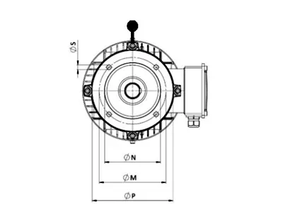
| Frame | FLANGE NUMBER |
P | M | N | S | L | LB | LC | T | D | DA | E | EA | F | FA | GC | GA |
|---|---|---|---|---|---|---|---|---|---|---|---|---|---|---|---|---|---|
| 80 | 100 | 120 | 100 | 80 | M6 | 340 | 300 | 340 | 3 | 19 | 19 | 40 | 40 | 6 | 6 | 21.5 | 21.5 |
| 90 S | 115 | 140 | 115 | 95 | M8 | 390 | 260 | 390 | 3 | 24 | 24 | 50 | 50 | 6 | 6 | 27 | 27 |
| 90 L | 115 | 140 | 115 | 95 | MS | 390 | 280 | 390 | 3 | 24 | 24 | 50 | 50 | 6 | 6 | 27 | 27 |
| 100 L | 130 | 160 | 130 | 110 | M8 | 450 | 320 | 450 | 3.5 | 28 | 28 | 60 | 60 | 6 | 6 | 31 | 31 |
| 112 M | 130 | 160 | 130 | 110 | M8 | 505 | 350 | 505 | 3.5 | 28 | 28 | 60 | 60 | 6 | 6 | 31 | 31 |
| Sl No | Kw | Frame Size | Rpm(Speed) | Load Current - Max(Amps) | Locked Torque In terms Of Full Load Torque(%) | Locked Torque In terms Of Full Load Current (Amps)(IE3) | Locked Torque In terms Of Full Load Current (Amps)(IE2) | Nominal Eff %(IE3) | Nominal Eff %(IE2) |
|---|---|---|---|---|---|---|---|---|---|
| 1 | 0.55 | 80 | 1440 | 1.7 | 170 | 650 | 600 | 80.8 | 77.1 |
| 2 | 0.75 | 80 | 1440 | 2.2 | 170 | 650 | 600 | 82.5 | 79.6 |
| 3 | 1.1 | 90 S | 1440 | 2.9 | 170 | 650 | 600 | 84.1 | 81.4 |
| 4 | 1.5 | 90 L | 1440 | 3.8 | 170 | 650 | 600 | 85.3 | 82.8 |
| 5 | 2.2 | 100 L | 1440 | 5.1 | 170 | 750 | 700 | 86.7 | 84.3 |
| 6 | 3.7 | 112 M | 1440 | 8.1 | 160 | 750 | 700 | 88.4 | 86.3 |